
Research on Three-Phase Partial Active Power Factor Correction
Yongxin Zhang, Xijun Yang, Jianguo Jiang, Shanghai Jiaotong University, China, zyx10601@163.com
Abstract
Higher power inverter-fed air-conditioners are powered by three-phase AC power supply with wide applications, bringing about the power factor correction (PFC) of three-phase rectifier. On the basis of brief analysis of three-phase one-switch partial active PFC, two three-phase partial active PFC’s are presented respectively for three-phase three-wire system and three-phase four-wire system, which is a hybrid PFC, incorporating active PFC and passive PFC techniques. After the short description of working principle and simulation analysis, the experiments are carried out. The obtained results prove the features of three-phase partial PFC of low voltage and current stresses, high efficiency, higher power factor and higher DC average voltage. The harmonics current are consistent with IEC61000-3-2 under any load, and the power factor is higher up to 0.98 under above medium load.
1. Introduction
In the inverter air conditioning industry, the application of the three phase AC-DC-AC inverter become wider and deeper. However, as threephase diode rectifier bridge and electrolytic capacitor is used as the pre-stage of this converter,under natural conditions, serious harmonic current pollution is produced at line side and the products can’t pass the IEC61000-3-2. In order to inhibit the harmonic current of the line side, unity power factor rectifier or power factor correction technology can be used as the pre-stage of the inverter.
At present, there are several types of rectifiers or power factor correction technology: (1) threephase not-controlled rectifier with passive LC filter.Advantages: good filtering effect, high efficiency,simple in principle. Disadvantages: bulky and heavy, LC series resonant in the no-load case and virtual-high DC voltage, generally buck type, its voltage
hardness is higher than that of natural rectifier.(2) Three-phase voltage controlled rectifier. Advantages: good correction effect, boost type,high voltage hardness, four-quadrant operation. Disadvantages: complex control theory, DC voltage is 1.3 ~ 1.5 times of the line voltage, large switching losses, small regulation range. (3)Three-phase current controlled rectifier. Advantages:good correction effect, buck type, high voltage hardness. Disadvantages: non-fourquadrant operation, complex control theory,large switching losses, DC voltage is lower than line voltage amplitude and it can be continuously adjusted downward. (4) Three-phase matrix controlled rectifier. Advantage: good correction effect,current type, buck type, DC voltage is lower than line voltage amplitude and it can be continuously adjusted downward, high voltage hardness, fourquadrant operation, it can be regarded as reverse-parallel of two three-phase current controlled rectifier. Disadvantage: complex control theory, large switching losses. (5) Threephase sparse rectifier. Advantages: good correction effect, current-source type, buck type, high voltage hardness, DC voltage is lower than line voltage amplitude and it can be continuously adjusted downward, four-quadrant or non-fourquadrant operation. Disadvantage: complex control theory, large switching losses. (6) threephase single-switch rectifier, three-phase twoswitch rectifier, three-phase three-switch rectifier. Advantages: low switching losses, simple control theory. Disadvantage: bad correction effect, nonfour-quadrant operation, simple control theory,buck type, low voltage hardness.
The additional costs of these rectifier circuits above mentioned are higher because they all use the filter inductor, rectifier bridge, inverter, or other switch components. In addition, filter inductances are very bulky and heavy. It's difficult to compare their costs in detail. It needs to analyze specific issues. For the inverter air conditioner,the efficiency of the whole machine (energy efficiency related), reliability, total cost controllability and other factors should be considered in addition to the current harmonic suppression effect. Therefore, this paper considers threephase three-switch rectifier program whose switches don't need high voltage withstanding.Two simple partial PFC programs are designed according to the difference between three-phase three-wire and three-phase four-wire power supply mode.
2. Three-phase Three-switch Partial Active PFC Analysis
2.1. Three-phase diode natural rectifier circuit
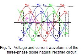
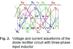
The voltage and current waveforms of the threephase diode natural rectifier circuit are shown in Fig. 1. The voltage and current waveforms of the diode rectifier circuit with three-phase input inductor are shown in Fig. 2. A power-cycle is divided into six intervals in accordance with phase voltage in the figure. Each interval is the Spartition method: one phase voltage is positive maximum and another is negative maximum at 30 before and after zero-crossing point of one phase voltage. Three phase voltage waveforms appear S-type.
For the three-phase non-controlled rectifier bridge, three line voltages exist before the bridge at one time. Six line voltage wave heads can set up rectifier process during one power cycle.Natural rectification appears only at one line voltage wave head in a 60° interval, that is, two phase voltages participates, another idle. So it results in that the continuous conduction angle is less than 120° and three-phase input current distorts.Discontinuous current spikes appear in the positive half-cycle or negative half-cycle of line side phase current in case of natural rectifier.Waveform factor decreases and power factor is low. Passive or active strategy is used to improve input current waveform. It can increase the continuous or discontinuous conduction angle of rectifier bridge diodes and the conduction angle of filter inductance. In addition, it can make the waveform of the instantaneous average of input current close to sinusoidal shape.
2.2. Three-phase Single-switch PFC circuit
The circuit structure of three-phase single-switch Partial Active PFC is shown in Fig. 3. In this figure,B1 is three-phase diode rectifier bridge, E1 is filter capacitor, D1 is reverse fast recovery diode,L1~L3 are three-phase filter inductance, S1 is reverse conducting power switch. Detection circuit of DC voltage and DC current is shown in this figure too.

Consider to this circuit structure, PWM pulse mode is designed as Fig. 4 according to Fig. 1 and 2, so it can bring in satisfactory input current waveform. In a power cycle(take phase A for example),the pulse regulation is that PWM driving pulse with appropriate duty is sent in the 2nd, 4th,6th, 8th, 10th and 12th range of 30°.
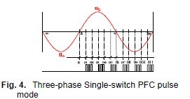
This modulation mode has such characteristics as follows: (1) The power switches works in partial time, so the efficiency of the rectifier circuit is higher; (2) Power line voltage may be shorted by pairs of inductors. (3) The distribution of duty cycle is related to the size of the load and inductance.The pulse duty cycle is wider when the load is heavier. (4) It’s classified as active PFC.The rectifier control is not decoupled. The power factor of the line side is less than that of 1. (5) It's generally BUCK-type AC-DC converter according to forced and natural rectification process.The voltage withstanding value of the power switches should be considered as 1200V.
2.3. Three-phase four-wire threeswitch Partial Active PFC circuit
Three switches partial active PFC circuit structure under three-phase four-wire system is shown in Fig. 5. In this figure, B1 is three-phase diode rectifier bridge, E1 is filter capacitor, L1~L3 are three-phase filter inductance, S1~S3 are three bi-directional controllable power switches.The characteristics are that DC circuit uses a single capacitor to filter. The input terminals of S1~S3 are connected to the output terminals of L1~L3 and their output terminals are connected to phase N after connected together. Detection circuit of DC voltage and DC current is shown in this figure too.
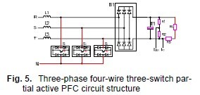
Consider to this circuit structure, PWM pulse mode is designed as Fig. 6 according to Fig. 1 and 2, so it can bring in satisfactory input current waveform. In a power cycle(take phase A for example),the pulse regulation is that PWM driving pulse with appropriate duty is sent in 30° before and after zero-crossing point of phase voltage and 30°after peak of phase voltage.
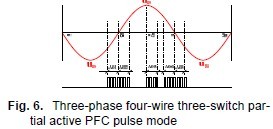
This modulation mode has characteristics as follows:(1) It uses neutral line whose current is not always zero; (2) The voltage withstanding value of the power switches are considered as only 600V. Other characteristics are the same as that of three-phase single-switch PFC circuit.
2.4. Three-phase three-wire three switches Partial Active PFC circuit
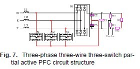
Three switches partial active PFC circuit structure under three-phase three-wire system is shown in Fig. 7. In this figure, B1 is three-phase diode rectifier bridge, E1 is filter capacitor, L1~L3 are three-phase filter inductance, S1~S3 are three bi-directional controllable power switches.DC circuit uses double capacitors E2 and E3 connected separately except for filter capacitor E1. The output terminals of S1~S3 are connected to the common terminal of E1 and E2 after connected together.
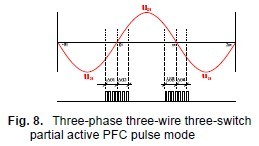
Consider to this circuit structure, PWM pulse mode is designed as Fig. 8 according to Fig. 1 and 2, so it can bring in satisfactory input current waveform. In a power cycle(take phase A for example),the pulse regulation is that PWM driving pulse with appropriate duty is sent in 30° before and after zero-crossing point of phase voltage.
This modulation mode has such characteristics as follows: (1) It doesn’t use neutral line; (2) The voltage withstanding value of the power switches are considered as only 600V. Other characteristics are the same as that of three-phase singleswitch PFC circuit.
3. Simulation Analysis of
Three-Phase Partial Active PFC
The circuits in Fig. 3, 5 and 7 are built by use of MATLAB/SIMULINK. The filter inductances are all 10mH. The filter capacitors E1 are all 1360μF.The filter capacitors E2 and E3 are 330μF. The circuits are simulated and analyzed according to the power and the PWM driving pulse regulation of Fig. 4, 6, 8. The power can be determined by the average of the product of DC voltage and DC current. the duty ratio of PWM pulse is regulated by the size of the average value. Three-phase AC input voltage is 380V, whose powerfrequency is 50Hz.
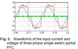
The waveforms of the input current and voltage of three-phase single-switch partial PFC are shown in Fig. 9 when the load is 5.5kW. The average of DC voltage is 537.5V. The peak-peak value of the ripple is 1.5V. The proportion of harmonic is obviously higher because the current waveform is square. So three-phase singleswitch PFC circuit is only suitable for the applications below several kW.
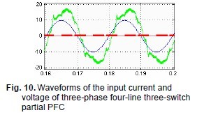
The waveforms of the input current and voltage of three-phase four-line three-switch partial PFC are shown in Fig. 10 when the load is 5.5kW. The average of DC voltage is 515V. The peakpeak value of the ripple is 15V. The proportion of harmonic is obviously lower because the current waveform is close to sinusoidal shape. But current pulse flows through the neutral line.
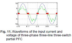
The waveforms of the input current and voltage of three-phase three-line three-switch partial PFC are shown in Fig. 11 when the load is 2.75kW. The average of DC voltage is 505V.The peak-peak value of the ripple is 2.0V. The proportion of harmonic is obviously lower because the current waveform is close to sinusoidal shape.
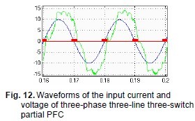
The waveforms of the input current and voltage of three-phase three-line partial PFC are shown in Fig. 12 when the load is 5.5kW. The average of DC voltage is 475V. The peak-peak value of the ripple is 2.5V. The proportion of harmonic is obviously lower because the current waveform is close to sinusoidal shape. So three-phase fourline partial PFC circuit is suitable for the applications of higher power.
4. Experimental Analysis of Three-Phase Three-Switches Partial Active PFC
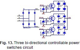
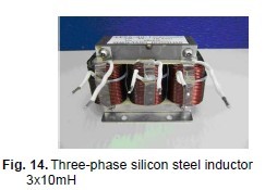
The experiment is carried out in order to verify the above theoretical analysis and simulation analysis. Some experimental results are given by taking three-phase three-line partial PFC circuit for example. 16-bit microcontroller NEC μpd78F1213 is chosen as controller. The whole circuit includes several parts as follows: controller and peripheral circuits, DAC conversion circuit based on DAC8560, AC voltage and AC current detection circuit based on voltage transformer and HALL current sensor, three-phase rectifier and three bi-directional controllable power switches circuit shown as Fig. 13, power up circuit using current-limiting resistor, bidirectional switches drive circuit, DC voltage and DC current detection circuit based on linear isolation amplifier HCPL7520. The photo of threephase input filter inductor using silicon steel is shown in Fig. 14.
The microcontroller calculates the product of DC voltage and current and output power and estimates the active component of AC-side current to determine the PWM driving pulse regulation after the voltage and current of AC and DC circuits are detected. Considering that large inductance can suppress the high-order harmonic effectively and higher harmonic content is relatively low, the microcontroller calculates RMS of the main AC current harmonic current (5, 7, 11, 13, etc.) and compares with the harmonic current standard. If RMS of every harmonic current is less than 90% of the standard value, the PWM driving pulse regulation under this input voltage and output power conditions is considered feasible, otherwise it needs to adjust the PWM pulse properly. Finally, it needs to verify whether the distribution of the various harmonic current fully meets the standards or not by power analyzer.DAC conversion circuit uses IIC bus. It can be used for real-time monitoring input voltage,input current, DC voltage and DC current and other signals.
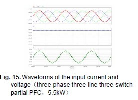
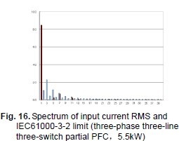
Three-phase AC input voltage is 380V, whose power-frequency is 50Hz. The waveforms of the input current, voltage and output voltage of three-phase three-line partial PFC are shown in Fig. 15 when the load is 5.5kW. The average of DC voltage is 515V. The peak-peak value of the ripple is 2.5V. The amplitude of fundamental current is 11.6A, whose RMS is 8.2A. It’s clear that the current waveform is close to sinusoidal shape. The proportion of harmonic is lower and consistent with the simulation results. The spectrum of input current RMS is shown in Fig. 16.The input current harmonics RMS are below the IEC61000-3/2 limit. The power factor is 0.98.
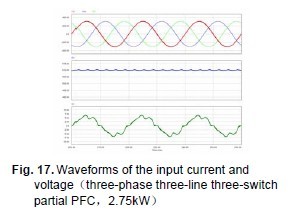
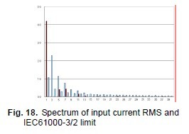
Three-phase AC input voltage is 380V, whose power-frequency is 50Hz. The waveforms of the input current, voltage and output voltage of three-phase three-line partial PFC are shown in Fig. 17 when the load is 2.75kW. The average of DC voltage is 510V. The peak-peak value of the ripple is 2.5V. The amplitude of fundamental current is 5.94A, whose RMS is 4.2A. It’s clear that the current waveform is close to sinusoidal shape. The proportion of harmonic is lower and consistent with the simulation results. The spectrum of input current RMS is shown in Fig. 18.The input current harmonics RMS are below the IEC61000-3/2 limit. The power factor is 0.98.
5. Conclusions
Three kinds of three-phase partial active PFC technology have been discussed. Single-switch partial PFC technology is the simplest of the three. But its harmonic current suppression effect is poor. So it can only be applied for small power load applications. Three-phase four-wire three-switch partial active PFC technology is a little complicated. Its harmonic current suppression effect is better. DC side doesn’t need split capacitors but it needs neutral line whose current is not always zero. Applications need to consider the neutral current. Three-phase three-wire three-switch partial active PFC technology is simplified. Its harmonic current suppression effect is better. DC side needs split capacitors and doesn’t need neutral line. It has a wide range of applications. Compared with three-phase voltage-type PWM rectifier, three-switch partial active PFC technology has small voltage and current stress, high efficiency, high power factor,high DC average voltage and other characteristics.The input current harmonics of AC side meet the IEC61000-3-2 standard under every kind of load. It is suitable for three-phase AC power inverter applications less demanding the line side current waveform.
6. Literature
[1] IEC61000-3-2: 1995 “Electromagnetic compatibility Part3: limits-set.2: limits for harmonic current emission (equipment input current≤16A per phase)” .
[2] Yang Xinghua. Analysis and Implementation on Novel Partial Active Power Factor Correction Circuit. Electrotechnical Application, 2007, 26(7): 54~57.
[3] Zhang Chongwei, Zhang Xing. PWM rectifier and its control. Beijing: Machinery Industry Press,October 2003 version 1.
[4] Lu Qiusheng. Power Factor Correction Technology and Application. Beijing:Machinery Industry Press, March 2006 Version 1.
[5] Zhou Zhimin, Zhou Jihai, Ji Aihua. Switching Power Supply Power Factor Correction Circuit Design and Application. Beijing:Posts & Telecom Press, August 2003 Version 1.
[6] Wu Jingchang. Power system harmonics.Beijing: China Electric Power Press, May 1998 Version 1.
[7] Lin Haixue, Sun Shuqin. Harmonics in power network. Beijing: China Electric Power Press, April 1998 Version 1.
[8] Qu Xueji, Qu Jingkai, Yu Mingyang. Rectifier Power Electronics Technology and Application. Beijing: Electronics Industry Press, April 2008 Version 1.
[9] Wang Jiuhe. Non-linear voltage-controlled PWM rectifier. Beijing: Machinery Industry Press. November 2008 version 1.
[10] Tsung-Cheng Chen. New AC/AC converters and applications to induction motor drives.Ph.D. dissertation. Department of Electrical Engineering. National Tsing Hua University.1993.