
A Novel Spread Spectrum Method for CCM Boost PFC Converters to Optimize both EMI and Efficiency Performance
Jian Chen, Jun Yabuzaki, Hiroyuki Oota
Fuji Electric Co.,Ltd., 4-18-1, Tsukama, Matsumoto, Nagano 390-0821, Japan
Hideo Shimizu
Fuji Electric Co.,Ltd., 1, Fuji-machi, Hino-shi, Tokyo, 191-8502, Japan
Abstract
This paper presents a novel spread spectrum method for Continuous Conduction Mode (CCM) boost PFC converter operating in average current mode control to optimize both conducted EMI and efficiency. The proposed method provides a saddle-type frequency modulation with maximum and minimum frequency limits. By the saddle-type frequency modulation, the improved conducted EMI performance is obtained without the sacrifice of efficiency, resulting in a simplified conducted EMI filter experimentally.
1 Introduction
In applications of active PFC converters, it is popular to use the boost PFC converters as an economical solution to comply with the IEC 1000-3-2 low frequency EMC standard. In applications of higher than about 200W output, we usually use aCCM boost PFC converters operating in average current mode with fixed switching frequency. It is worth noting that the CCM boost PFC converters may operate in CCM, Critical Conduction Mode (CRM) or Discontinuous Conduction Mode (DCM) depending on the boost inductor value, the input line voltage, the switching frequency and so on[1].
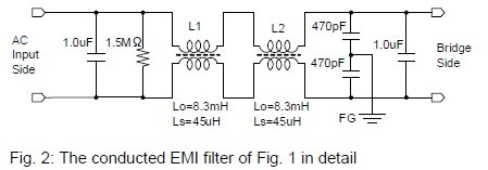
Since the boost PFC converters are one kind of SMPS operating in high frequency range, it is almost necessary to use conducted EMI filters in compliance with the CISPR-22 standard. In a universal application with 600W output, Fig. 1 shows a typical CCM boost PFC converter operating in the switching frequency of no more than 70kHz, where a conducted EMI filter with two choke coils is placed and shown in Fig. 2 in detail where the choke coils have open inductance of 8.3mH and short inductance of 45uH.
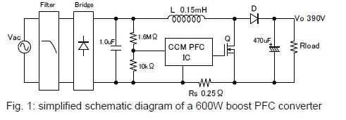
In order to simplify the conducted EMI filter, using relatively higher switching frequency, such as 65kHz~70kHz, is effective since the farer away the 3rd harmonic component of the current ripple is from 150kHz, the better the effect of the EMI filter is [2]. However, it is coming up with higher switching loss, especially in the case of low input line voltage. It has also been studied to use spread spectrum techniques operating in relatively higher frequency at the peak of input line voltage, which as well increase the switching loss due to relatively higher turn-on and turn-off inductor current [3].
In this paper, a novel spread spectrum method is proposed to reduce the generation of the conducted EMI to simplify the EMI filter without the sacrifice of the efficiency. This paper is organized as follows. First of all, the 3rd harmonic component of the current ripple of the boost inductor is calculated by Fourier Transform in terms of input line voltage and then a new spread spectrum method is described. Secondly, Comparison between the modulated switching frequency and the conventional fixed switching frequency is implemented with experimental data of the conducted EMI and efficiency. Finally, the main work is summarized.
2 Analysis
In the application of Fig. 1, since the current ripple waveform of the boost inductor is triangular as shown in Fig. 3, the 3rd harmonic component of the current ripple may be analyzed by Fourier Tranform.
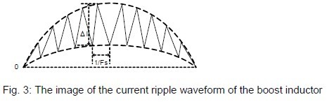
The current ripple of the boost inductor is given by
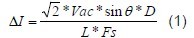
here Vac and θ is the effective value and the phase of the input line voltage respectively, L is the inductance of the boost inductor, Fs is the switching frequency and D is the duty of the switching cycle which is defined as
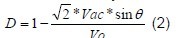
here Vo is the output voltage of the boost PFC converter.
When we do the Fourier analysis on the current ripple of the boost inductor, the 3rd harmonic component of the current ripple can be obtained.
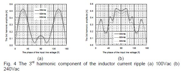
In the case of 100Vac and 600W, the amplitude of the 3rd harmonic component is shown in Fig. 4 (a) which illustrates the worst-case value takes place at the phase of around 30º and 150º instead of around 90º. Therefore, it’s enough just to increase the switching frequency at the phase of around 30º and 150º to reduce the 3rd harmonic amplitude.
In the case of 240Vac and 600W, the 3rd harmonic amplitude is shown in Fig. 4 (b) where the worst case appears at the phase of around 90º. So, it is important to increase the switching frequency in the vicinity of 90º in order to reduce the 3rd harmonic amplitude. It is worth noting that Fig. 4 (b) is calculated by taking into account the discontinuous boost current which appears in the case of high input line voltage due to low inductance value of the boost inductor.
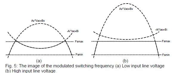
According to the above analysis, it is proposed to modulate the switching frequency as a function of the input line voltage (Vac) and the input line current (Iac) with maximum (Fsmax) and minimum (Fsmin) frequency limits. The modulated switching frequency (Fs) is given by

where Av, Bv, Ai and Bi are positive constants. The image of the modulated switching frequency is shown in Fig. 5.
3 Experimental result
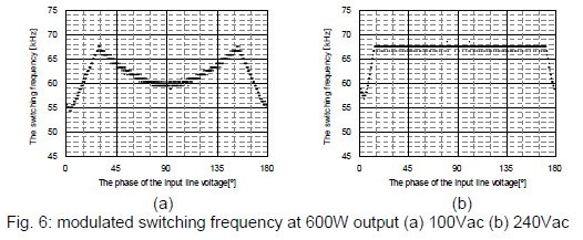
In the application of Fig. 1, using Fuji’s spread spectrum PFC controller FA5613 based on equation (3), the modulated switching frequency is shown in Fig. 6. In the case of 100Vac, a saddle-type switching frequency is obtained to keep the efficiency performance due to 60kHz at 90º and to reduce the generation of the conducted EMI due to 68kHz at 30º and 150º. In the case of 240Vac, it mainly works on the maximum frequency limits to reduce the EMI without efficiency issue owing to lower inductor current.
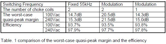
In terms of the worst-case quasi-peak margin and the efficiency recorded in Table 1, it is clear that one choke coil in Fig. 2 can be removed by the comparison between fixed 55kHz switching frequency with two choke coils and modulated switching frequency with one choke coil.
4 Conclusion
In this paper, the 3rd harmonic component of the inductor current ripple depending on the input line voltage is investigated for the CCM boost PFC converters. A novel spread spectrum method to reduce the generation of the conducted EMI without the sacrifice of efficiency is proposed. By making measurements on a practical 600W boost PFC converter, in terms of the performance of the conducted EMI and the efficiency, we found that one choke coil of the EMI filter may be removed due to the proposed spread spectrum method.
5 References
[1] Philip C. Todd, “UC3854 Controlled Power Factor Correction Circuit Design”, Texas Instruments Co.
[2] Bing Lu, Wei Dong, Shuo Wang, F.C.Lee, “High Frequency Investigation of Single-switch CCM Power Factor Correction Converter”, IEEE, 2004
[3] Mike O’Loughin, “PFC Pre-Regulator Frequency Dithering Circuit”, Texas Instruments Co., 2007