
Bearing Damage Detection in Speed-sensorless Operated
Multi-Mass-Systems
Dipl.-Ing. Henning Zoubek, Universität Siegen, henning.zoubek@uni-siegen.de
Prof. Dr.-Ing. Mario Pacas, Universität Siegen, pacas@uni-siegen.de
Abstract
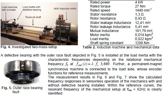
The present paper deals with the diagnosis of outer-race bearing faults in a speed-sensorless operated drive. Frequency response measurement of the mechanical two-mass-system serves as instrument for the detection of the bearing failure. Deterministic deviations from the measured curve without failure point out the presence of an outer race bearing fault even when calculated with the estimated speed from a speed-adaptive Luenberger observer structure in sensorless operation.
1. Introduction
Methods for the operation of speed-variable drives without the need of a rotational transducer have become popular topics in research and industry during the last decades due to the improvements in cost and reliability they bear [1]. The ongoing acceptance of such sensorless control methods leads to the question of their applicability to important drive features as e.g. automatic commissioning, system diagnosis and so forth. With respect to the problems related to the operation of drives where the elasticity of the shaft cannot be neglected, the speed-sensorless operation of such multi-mass systems still has to be investigated more in detail. Identification procedures for multi-mass-mechanics are essential steps for the modeling of the plant and therefore build the cornerstone for the controller design and further commissioning procedures. The frequency response calculation of the mechanical system is a reliable method that yields already excel ent identification results in drives operated withangular speed sensors [2].
Bearing faults are a main factor for unplanned downtimes of plants. Diagnosis methods that allow the detection of advancing bearing failures are therefore considered as additional, valuable tools to increase the reliability of the drive. As former studies have shown, the frequency response measurement for multi-mass-systems gives the feasibility to reliably detect bearing failures in speedvariable drives with installed encoder [3]. The following chapters investigate the bearing fault diagnosis capability of the frequency response measurement for two-mass-systems under speed-sensorless operation conditions.
2. Speed-Sensorless Control
To achieve the speed control of speed-variable drives without an installed rotational transducer,several methods have been employed and improved during the last years [1]. They can be distinguished in two fields:
• Methods with signal injection and
• fundamental-wave-based structures.
The former inject additional test-signals into the machine and employ the machine response to utilize anisotropies of the rotor as indicator for the actual machine position [4]-[7]. A great advantage of the signal injection based schemes lies in the stable operation at zero stator frequency, which is a challenge for induction machines that become unobservable at this operation point [1].
Nevertheless, these methods are highly sophisticated and a distinction of different anisotropies is often difficult, so that a speed detection becomes complicated [1], [4].
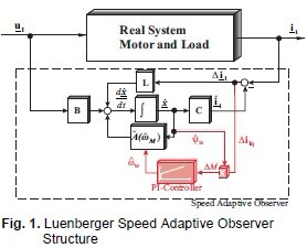
The second methods use fundamental-wave based models of the machine to estimate the actual speed or position value [8]-[10]. Open loop models, model reference adaptive systems (MRAS), or observer structures are common approaches to employ the machine equations in order to extract the desired speed information [1]. Drawbacks of these methods are the afore mentioned problems for induction machine operation around zero stator frequency and the temperature dependency of the model parameters e.g. the stator and rotor resistances. Combined with parameter adaption schemes for the varying model parameters, the fundamental wave based methods allow a good control behavior of induction motors. Especially speed adaptive Luenberger observer structures yield very good dynamic behavior of the drive over a wide speed range [9], [10]. Hence, a speed-adaptive Luenberger observer estimates the speed of the induction machine in this paper. The stator currents i1d,q and the rotor flux ψ2d,q serve as state variables. The full observer structure is depicted in Fig. 1.
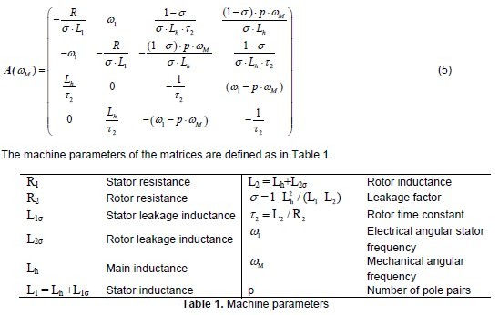
Based on the machine equations, the induction motor can be described in the state space by the following equations (1)-(5) in a rotor-flux oriented, synchronous rotating d-q-reference frame:
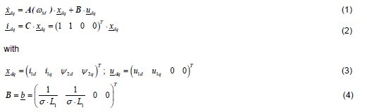
And the system matrix A(ωM), which depends on the electrical parameters of the induction machine and the angular mechanical frequency ωM.
From (1)-(5), the Luenberger speed-adaptive observer in Fig. 1 can be built and is given by (6)-(8) with the estimated mechanical angular frequency ωˆM:

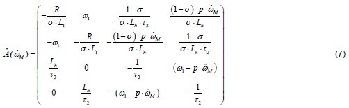
L indicates the observer feedback matrix, which is designed similar to [10]. The system matrix Aˆ ˆωM)in Fig. 1 depends on the actual estimated mechanical angular frequency, which is calculated regarding (8).
The speed estimation is carried out through a PI-adaption structure, which has the estimation error of the q-component of the stator current Δ =i1qi1q − i1q as input multiplied with the estimated rotor flux ψˆ2d [10]. The so adapted angular mechanical speed is fed back to the system matrix Aˆ ˆM) . This speed information is used for the control as well as for the identification procedure of the two-mass-system in this paper. Voltage sensors are not needed for this approach as the reference values from the current controller outputs can be exploited.
3. Frequency Response Measurement as a Bearing Fault Detection Strategy
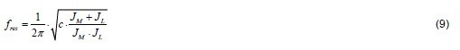
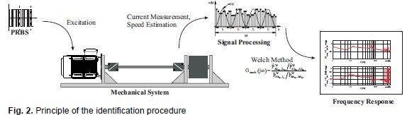
Multi-mass-systems are built up by non-rigid connections of several inertias and are therefore able to perform torsional oscillations. The correct modeling of such systems is necessary for the optimization of the drive system, so the controllers can be designed in a manner that the desired system behavior is achieved e.g. damping of undesired oscillations. While the inertias might be known parameters in such drives, at least the spring constant values of the shafts are usually not available. As former studies have shown, the identification of these mechanical parameters of multi-mass-systems can be well achieved with the help of frequency response calculation of the mechanical system [2]. For this purpose the system is excited with Pseudo-Random-Binary-Signals (PRBS) as an additional disturbance in the torque-generating component of the stator current i1q and the response is measured in the mechanical angular machine speed ωM. The frequency response can afterwards be calculated by means of the Welch-method [2]. A great advantage of this identification procedure is that it can be carried out during the normal operation of the plant in closed loop speed control and an excitation of the resonant frequency is avoided at any time. The resonant frequency of a two-inertia-setup is defined by the mechanical parameters: motor and load inertia JM and JL, respectively, and the spring constant c of the shaft as given by (9).
With respect to the identification of the sensorless operated drive, the estimated speed ωˆM from the speed-adaptive observer is now utilized instead of the measured value for the frequency response calculation. Fig. 2 shows the principle of the speed-sensorless identification procedure for a mechanical two-mass-system that has the calculated frequency response of the mechanical system as output. From the resulting Bode-diagram, the mechanical resonant frequency fres is directly visible [11], which can serve for the modeling of the plant.
Condition monitoring methods can highly increase the reliability of plants. An early detection of malfunctions in the drive allows maintenance procedures to be arranged before the system fails to operate. Bearing failures turn out to be the most common reason for unplanned downtimes of plants [12], [13], [14]. As an indicator for an incipient bearing failure, the so called characteristic fault frequencies can be exploited. Considering vibration measurements, it is obvious that each time a ball of the bearing passes a defective area on the raceways, the resulting impact leads to an increase of the machine vibration. For a constant mechanical speed, corresponding fault frequencies can therefore be determined for different types of failures [12], [15]. Further, torque and speed disturbances as well as air gap variations are an outcome of the bearing defect [12], [13]. Based on these effects of the bearing damage on the affected drive, different methods have been proposed in recent years that allow an early detection of the fault so that maintenance procedures can be carried out to avoid a downtime of the plant:
One of the standard condition monitoring procedures for bearing damage detection relies on vibration measurements on the drive [13], [15]. Though the achieved results are very accurate and early damage detection is possible, the need for the additional accelerometers increases the installation costs. To overcome the necessity of supplementary sensors, certain methods try to exploit the information from the standard sensors of the drive. Here, Motor Current Signature Analysis (MCSA) [12], [14] has become a popular task in the last years. The signals from the stator current measurement serve as a basis for the bearing damage detection. Signal processing methods such as filters, neural networks or statistical analysis extract the presence of the fault frequencies from the stator current as an indicator for a present fault.
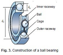
The frequency response measurement of the mechanical system with installed encoder has already presented its feasibility to diagnose advancing bearing defects utilizing only the standard sensors for speed-variable drives [3]. As a basis for the modeling of the plant and the controller design for the control of multi-mass-systems, the frequency response measurement is carried out during the commissioning of the drive. At this state, no bearing failure is supposed to exist in the drive. Hence, the resulting curve can be utilized as reference for the condition monitoring. Compared to this reference, a bearing defect becomes clearly visible at deterministic deviations on the characteristic fault frequencies of the bearing defect and its multiples. For an outer race bearing fault, which will be investigated in the following, the characteristic fault frequency can be calculated according to (10).
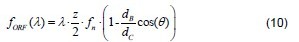
where λ = 1,2,3,…, fn is the rotational frequency of the drive, z is the number of balls, dB and dC are the ball and cage diameter, respectively, as in Fig. 3. θ assigns the ball contact angle than can be assumed to be zero for radial ball bearings.
The following experimental results point out the effectiveness of the frequency response measurement for condition monitoring purposes when carried out in speed-sensorless operation for the case of a present outer race bearing fault in the drive.
4. Experimental Results
The inveestigated two-mass-system with a resonant frequency of fres = 62Hz consists of a 4kW inductionn motor connnected to a lo oad side inerrtia by a non-rigid shaft as in Fig. 4. TThe drive parameters are givenn in Table 2.. The control of the drive including thee speed ada adaption is carriied out on a dSPACE prototyping platform.. The inverter is switchedd with a PWM frequency of 5 kHz, whhich also corresponds to the daata acquisition rate of the machine cuurrents.
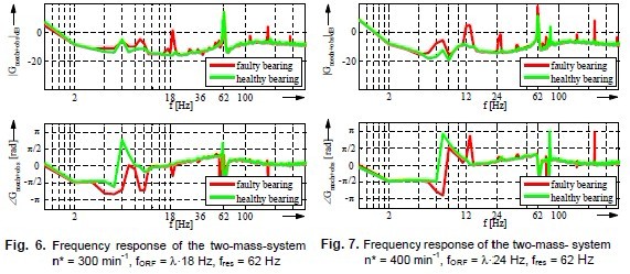
For the purpose off condition monitoring, the curve with installed bearing faault show ssignificant deviationns from this rreference at the characteeristic fault frrequencies for the amplitude as well as in the phhase diagram or the outer rrace bearing defect in
Hence, tthe frequenccy response measuremeent of a multii-mass-syste allows a deterministic outer race fault bearingg damage deetection.
5. Conclusion
The results presented in this paper show that the identification procedure for two-mass-systems by frequency response measurement is capable to detect outer-race bearing failures with the estimated speed information during speed-sensorless operation. Besides the possibilities as an identification method during the commissioning of drives, the presented method is considered as a valuable tool to increase the reliability of plants as it combines advantageous speed-sensorless control techniques with condition monitoring aspects. Further investigations with different faults and defect motor bearings shall underline the reliability of the bearing fault diagnosis possibilities for sensorless operated drives.
6. Literature
[1] J. Holtz, “Sensorless Control of Induction Machine – With or Without Signal Injection?”, IEEE Trans. Ind. Electron., Vol. 53, No. 1, Feb 2006
[2] S. Villwock, M. Pacas, “Application of the Welch-Method for the Identification of Two- and Three-Mass-Systems”, IEEE Trans. Ind. Electron., Vol. 55, No. 1, Jan 2008
[3] S. Villwock, J. M. Pacas, “Detection of Rolling Bearing Faults by Frequency Response Analysis”, PCIM-Conference, Nuernberg, Germany,2007
[4] P. Garcia, F. Briz, M.W. Degner, D. Diaz-Reigosa, “Accuracy, Bandwidth and Stability Limits of Carrier-Signal-Injection-Based Sensorless Control Methods”, IEEE Trans. Ind. Appl., Vol. 43,No.41, Jul./Aug. 2007
[5] W. Hammel, R. M. Kennel, “Integration of alternating carrier injection in position sensorless control without any filtering”, IEEE Energy Conversion Congress and Expo (ECCE), San-José,California, 2009
[6] Y. Yoon, S. Sul, S. Morimoto, K. Ide, “ High Bandwidth Sensorless Algorithm for AC Machines based on Square-wave Type Voltage Injection”, IEEE Energy Conversion Congress and Expo (ECCE), San-José, California, 2009
[7] M. Schroedl, “Sensorless Control of AC Machines at Low Speed and Standstill Based on the INFORM Method”, IEEE Industry Applications Society Annual Meeting, 1996
[8] M. Depenbrock, C. Evers, “Model-Based Speed Identification for Induction Machines in the Whole Operating Range”, IEEE Trans. Ind. Electron., Vol. 53, No. 1, Feb 2006
[9] L. Harnefors, M. Hinkkanen, “Complete Stability of Reduced-Order and Full-Order Observers for Sensorless IM Drives”, IEEE Trans. Ind. Electron., Vol. 55, No. 3, March 2008
[10] S. Suwankawin, S. Sangwongwanich, “Design Strategy of an Adaptive Full-Order Observer for Speed-Sensorless Induction-Motor Drives – Tracking Performance and Stabilization”, IEEE Trans. Ind. Electron., Vol. 53, No. 1, Feb. 2006
[11] Zoubek, Henning; Pacas, Mario, "A method for speed-sensorless identification of two-mass-systems," IEEE Energy Conversion Congress and Exposition (ECCE), Atlanta, USA, 2010
[12] M. Blödt, P. Granjon, B. Raison, G. Rostaing, “Models for Bearing Damage Detection in Induction Motors Using Stator Current Monitoring, IEEE Trans. Ind. Electronics, Vol. 55, No. 4,April 2008
[13] J. R. Stack, T. G. Habetler, R. G. Harley, “Fault-Signature Modeling and Detection of Inner-Race Bearing Faults”, IEEE Trans. Ind. Applicat., Vol. 42, No. 1, Jan./Feb. 2006
[14] S. Nandi, H. A. Toliyat, X. Li, “Condition Monitoring and Fault Diagnosis of Electrical Motors-A Review”, IEEE Trans. Energy Conv,,Vol. 20, No 4, Dec 2005
[15] B. Li, Mo-Yuen Chow, Yodyium Tipsuwan, J. C. Hung, “Neural-Network-Based Motor Rolling Bearing Fault Diagnosis”, IEEE Trans. Ind. Electronics., Vol. 47, No. 5, Oct. 2000
Acknowledgement
The authors highly appreciate the support of the “Deutsche Forschungsgemeinschaft” (DFG) for the actual project and the ongoing research.