
Adaptive Active Capacitor Converter for Improving Stability of Cascaded DC Power Supply System
Xin Zhang, Nanjing University of Aeronautics and Astronautics, College of
Automation Engineering, Nanjing, Jiangsu Province, China.
Xinbo Ruan, College of Electrical and Electronic Engineering, Huazhong University of
Science and Technology, Wuhan, Hubei Province, China.
Abstract
Cascaded structure is a typical structure in a DC distributed power system. However,the interaction between its individually designed power modules/subsystems may cause instability problem of the whole system. This paper firstly analyzes its instability reason, then, proposes an adaptive active capacitor converter for improving the stability of cascaded DC power supply system. The proposed converter has the following features. First, the proposed converter equivalently increases intermediate DC bus capacitor to solve the stability problem of the cascaded system.Second, long lifetime is ensured because there is no electrolytic capacitor in the active capacitor converter. Third, the proposed converter works adaptively, keeping its loss minimal. Forth, it only needs to sense bus voltage of the system, which ensure a good versatility. A design procedure of the proposed converter is given. A 480W cascaded system with two Phase shifted Full bridge converters has been built and evaluated. The experimental results confirm the theoretical predictions.
1 Introduction
With power electronics playing more and more important role in industry, agriculture,national defense and other areas, low cost and short design period are required for the electronic products to meet the rapidly changing needs of the market. One of the effective ways to solve this problem is power electronics system integration, which can be divided into three levels, discrete component level integration, module-level integration and system-level integration[1].
Cascaded system is a classical combination of standardized converter modules in system-level integration [1], whose source converter and load converter are defined in Figure 1. Cascaded system has two advantages. First, considering the intermediate dc bus, the load converter can be placed as near as the load, so it has high-precision output voltage and fast dynamic response. Second, dc bus voltage may be appropriately increased to reduce the distribution losses which caused by the line impedance. So the conversion efficiency of the overall system is improved.However, the interaction between its individually designed modules/subsystems may cause instability problem of the whole system [2]. Therefore, the stability of the cascaded system has always been the focus of research.
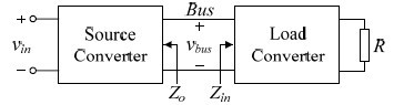 Fig. 1. Cascaded power supply system.
In 1976, Middlebrook pointed out that, if source converter’s output impedance is lower than load converter’s input impedance in the whole frequency range, the cascaded system is stable. This is the famous Middlebrook criterion. However, it is quite strict for engineers to design products. In order to solve this problem, many researchers proposed the concept of prohibited areas[3].
In fact, Middlebrook criterion and the concept of prohibited areas are essentially the same, that is, if the ratio of source converter’s output impedance and load converter’s input impedance meets the Nyquist criterion, the system is stable. According to this approach, many solutions have been proposed to solve cascaded system’s instability problem. In [4], Middlebrook criterion is used to design the intermediate line filter in a cascaded system. However, it is hard to design an intermediate line filter which both meet impedance compatibility and EMI specifications. In [5], it solves the stability problem from the control point of view, but it needs to sense inductor current or capacitor current of source converter, so its versatility is not good.
This paper presents a general solution to solve the instability problem of cascaded system. An adaptive active capacitor converter is introduced to the intermediate dc bus of cascaded system. It firstly only needs to sense bus voltage instead of understanding the structure of subsystems, which ensures good versatility. Second, it equivalent increases intermediate dc bus capacitor to solve the stability problem, whose function is easy to realize. Third, long lifetime is ensured, because there is no electrolytic capacitor in the active capacitor converter. Forth, the proposed converter works adaptively, which keeps converter’s loss minimal. A 480W cascaded system with two Phase shifted Full bridge converters has been built and evaluated. The experimental results confirm the theoretical predictions.
2 Stability of cascaded system
As shown in Fig. 1, if source converter works with single voltage loop, its closed-loop output impedance is expressed as[2],

where, in Buck, Boost and Buck-Boost type converter, Ls and Cs are inductor and capacitor, respectively, rLs and rCs are parasitic resistance of Ls and Cs ,respectively, Tvs is source converter’s voltage loop gain.
According to (1), it can be derived that source converter’s peak closed-loop output impedance Zo_peak appears in the cut-off frequency fcs of its voltage loop gain.
![]()
Load converter’s closed-loop input impedance equals[2],

where, in Buck, Boost and Buck-Boost type converter, L and C are inductor and capacitor, respectively, rL and rC are parasitic resistance of L and C, respectively, M is load converter’s voltage transfer ratio, which equals to D, 1 / (1−D) and D / (1−D) respectively, here, D is the duty cycle of converter, RLd is load converter’s load resistance, Tv is load converter’s voltage loop gain.
The ratio of source converter’s output impedance and load converter’s input impedance is equivalent to the loop gain of cascaded system[2], which expressed as
![]()
Obviously, if the amplitude of Zo is lower than Zin, the system is stable. But there are two cases when Zo and Zin are overlapped. First, the overlap frequency is lower or near fc_load. Second, the overlap frequency is higher than fc_load. However, only the first case could cause system instability because of Tm’s poor phase margin.
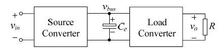 Fig. 3. Cascaded system with electrolytic capacitor.
3 Adaptive active capacitor converter
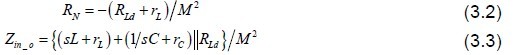
From (2), it can be seen that Zo_peak is inversely proportional to its output capacitor Cs,thus, increasing Cs can reduce Zo_peak, which can avoid overlap with load converter’s input impedance and ensure cascaded system stable. So Fig.3 shows a general industrial solution, which adding a bus capacitor Ce directly. The bus capacitor can be treated as the added output capacitor of source converter, so it can solves the instability problem. But, it has the following problems. First, the electrolytic capacitor should be used because large value of capacitor is needed to ensure system stable,which reduces system’s lifetime. Second, Fig. 3’s method is contrary to the purpose of system-level integration.
3 Adaptive active capacitor converter
From (2), it can be seen that Zo_peak is inversely proportional to its output capacitor Cs,thus, increasing Cs can reduce Zo_peak, which can avoid overlap with load converter’s input impedance and ensure cascaded system stable. So Fig.3 shows a general industrial solution, which adding a bus capacitor Ce directly. The bus capacitor can be treated as the added output capacitor of source converter, so it can solves the instability problem. But, it has the following problems. First, the electrolytic capacitor should be used because large value of capacitor is needed to ensure system stable,which reduces system’s lifetime. Second, Fig. 3’s method is contrary to the purpose of system-level integration.
this paper propose an adaptive active capacitor converter, which uses a noelectrolytic capacitor circuit instead of electrolytic capacitor. Its port current and voltage are capacitive and adjusted adaptively, which not only ensure the system stable, but also keeps its loss minimal. More importantly, this converter only needs to sense the bus voltage, thus, this method has good versatility.
Fig. 4 gives the structural relationship among source converter, load converter and the proposed converter in cascaded system. Many bi-directional converters can be employed for the circuit of active capacitor converter, such as Buck / Boost bidirectional converter, Push-Pull Full-Bridge bidirectional converter and so on.
Considering their principle and design are similar, Buck / Boost bidirectional converter is chosen as an example to analyze active capacitor converter’s design and control in this paper. Fig. 5 shows the main circuit, which is composed of Qa1 and Qa2, La and Ca.
Fig. 6 shows the control block diagram of adaptive active capacitor converter, its operation principle is as follows. The proposed converter first detects vbus, which reflects system oscillation, then, its output current ia is given by the adaptive detection circuit, which first satisfied ia= Ce·(dvbus/dt). It shows that Ce is proportional to active capacitor converter’s conduction current, so a larger Ce means a larger conduction loss. In practical, different load needs different Ce. So the adaptive control is necessary, which will be described detailed in next section. At the same time, the converter regulates va to make the circuit work well by regulator G1(s).
4 Design for adaptive active capacitor converter
4.1 Design for Main Circuit
First, discuss the value of Ce. Considering converter’s impedance will be changed with circuit parameters variations [6], stability margin should be guaranteed at least 6 dB between Zo and Zin to ensure cascaded system stable, it is described as follows.
![]()
Considering (2), (3) and (5), Ce meet (6), to reduce active capacitor converter’s power conduction loss and cost, Ce should be as small as possible. So Ce = Ce_min

As shown in Fig. 4, the dc bus voltage vbus is defined as


Combining (7) and (8), the instantaneous active power Pa is derived as

Compared to Vbus, Vos can be ignored, so Fig. 7 shows waveforms of vbus, ia and Pa.The required energy, which is provided or absorbed by the active capacitor converterin half period, is given as

a. The Value of Va
this paper chooses Va=2Vbus, which not only ensures good tracking effect, but also keep smaller voltage stress of Qa1 and Qa2.
b. Qa1 and Qa2
ia flows through Qa1 and Qa2, so the current stress of Qa1 and Qa2 is given.

Where, RfLd is load resistance at full load.
Then, appropriate switches can be selected by Va and (11).
c. Value of Ca
The energy, which needs Ca to provide, is described as (12),

Choose ΔVa=10% Va and design Ca at full load, by using (10), (12), so

Where, Ce_max is the value of Ce at full load.
This paper selects Ca = (VosCe_max)/ΔVa, so film capacitor can be employed instead of electrolytic capacitor, which ensures the high life of system.
d. Switching frequency fs and Value of La
ia is ac current, its frequency is fos. In order to ensure good tracking effect of ia, fs should be satisfied fs≥10fos. Considering Δia=20%ia, La is described as follows

4.2 Design for the Control Circuit
 Fig. 8. Circuit for adaptive control.
Fig. 8 gives the adaptive detection circuit for the reference current of ia, which includes three parts. Circuit A is the adaptive circuit for amplitude of ia. Circuit B is the differential circuit of vbus, which determines the characteristics of ia. Circuit C gives the final reference current of ia.
5 Experimental Results
A 480W cascaded system (360V-48V-12V) with two Phase shifted Full bridge converters has been built and evaluated. The source converter and load converter are both stable independently but unstable in cascaded system. With and without active capacitor converter, the experimental waveforms of load current io, ac component of bus voltage vbus and ac component of system’s output voltage vo2 at full load and 50% load are given in Figs. 9 and 10.
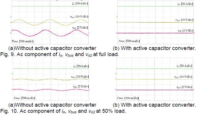
Fig.11 shows the load current io, reference current of La and actual current of La of active capacitor converter, with load changing between full load and 50% load. It demonstrates the adaptive dynamic function of the active capacitor converter.
The experimental results confirmed the above theoretical predictions. The experimental results prove that, the proposed converter not only solve the instability problem of the cascaded system, but also has good adaptive characteristics.
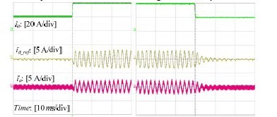
Fig. 11. io, iLa_ref and iLa with load changing between full load and 50% load.
6 Conclusion
This paper first analyzes the cause for instability cascaded system, if the overlap,which between source converter’s Zo and load converter’s Zin is appearing with the bandwidth of load converter’s voltage loop gain, the phase margin of Tm is less than zero and the cascaded system is unstable. Then, the adaptive active capacitor converter, which improving the stability of cascaded dc power supply system, is proposed. The characteristics of its port current and voltage are the same with an electrolytic capacitor, but there is no electrolytic capacitor in its circuit. So the proposed converter not only can solve the instability problem but also ensure system’s long lifetime. In additional, the active capacitor converter is adaptive control, which keeps the loss minimal at full load range. More importantly, this method only needs to sense the bus voltage, which has a good versatility. The circuit parameters and adaptive control circuit are described in detail. A 480W 360 V-48 V- 12V cascaded system’s instability problem is solved by the proposed converter. The experimental results prove that, the proposed converter not only solve the instability problem of the cascaded system, but also has good adaptive characteristics.
REFERENCES
[1] J. D. Van Wyk and F. C. Lee, “Power electronics technology ― Status and future,” in Proc. CPES, 1999, pp. 61-70.
[2] R. D. Middlebrook, “Input filter considerations in design and application of switching regulators,” in Proc. IEEE IAS, 1979, pp. 366-382.
[3] C. M. Wildrick, F. C. Lee, B. H. Cho and B. Choi, “A method of defining the load impedance specification for a stable distributed power system,” IEEE Trans. Power Electronics, vol. 10, no. 3, pp. 280-285, 1995.
[4] B. Choi, and B. H. Cho, “Intermediate line filter design to meet both impedance compatibility and EMI specifications,” IEEE Trans. Power Electronics. vol. 10, no.5, pp. 583-589, 1995.
[5] A. M. Rahimi and A. Emadi, “Active damping in dc/dc power electronic converters:a novel method to overcome the problems of constant power loads,” IEEE Trans.Industrial Electronics, vol. 56, no. 5, pp. 1428-1439, 2009.
[6] C. M. Wildrick, “Stability of distributed power supply system,” Ph.D. dissertation,Virginia Polytech. Inst. State Univ., Blacksburg, VA, Feb. 1993. 160